The Quest for IBM PS/2 Tower 5.25 Drive Bay Bezels

How do you fill a hole in a computer’s heart? Here, in Userlandia, the solution is 3D prints.

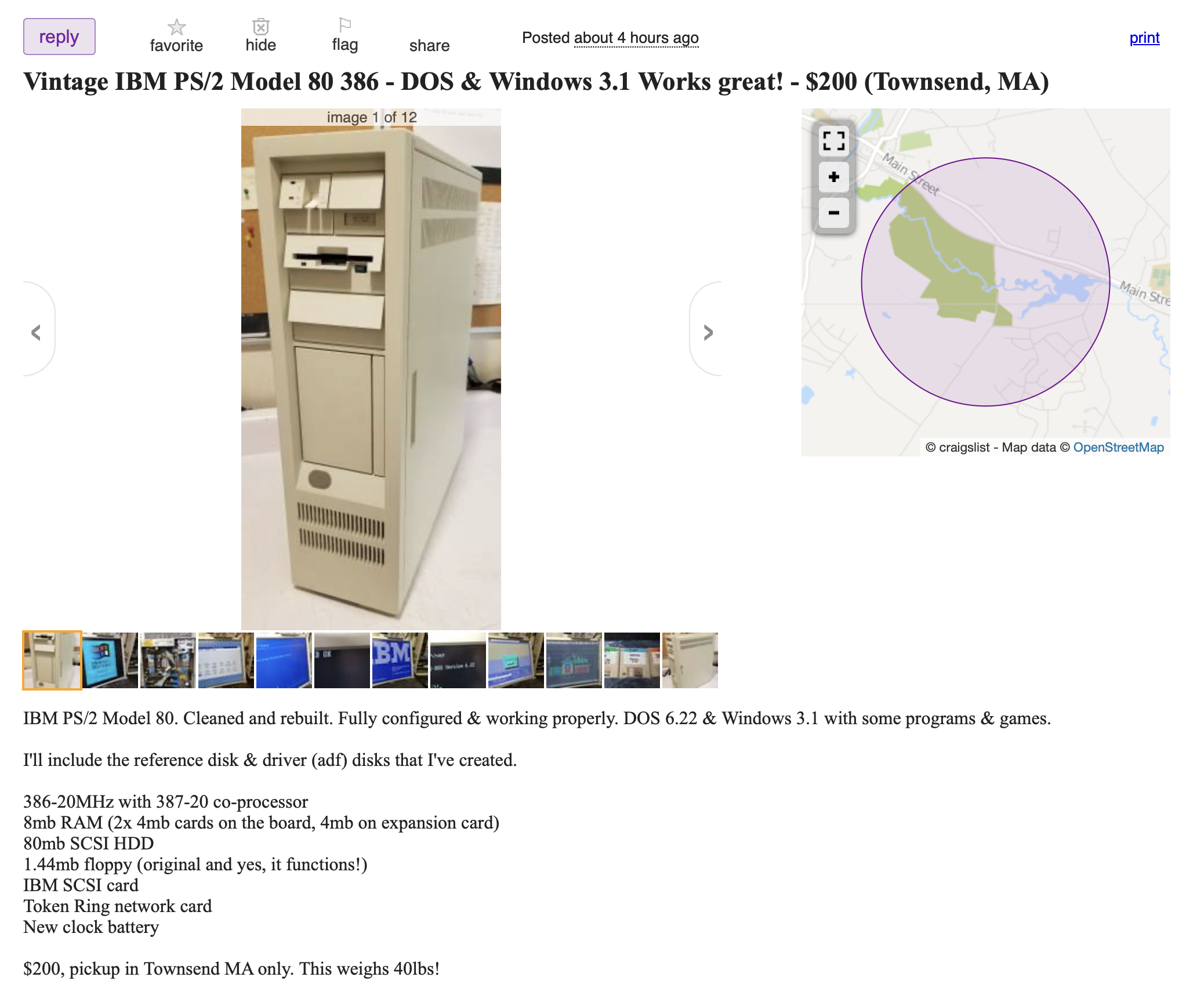
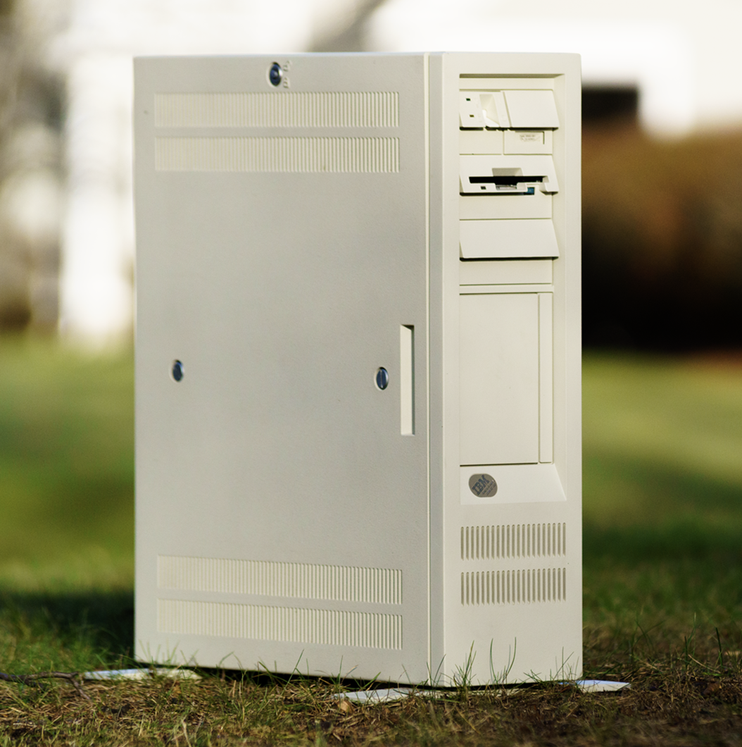
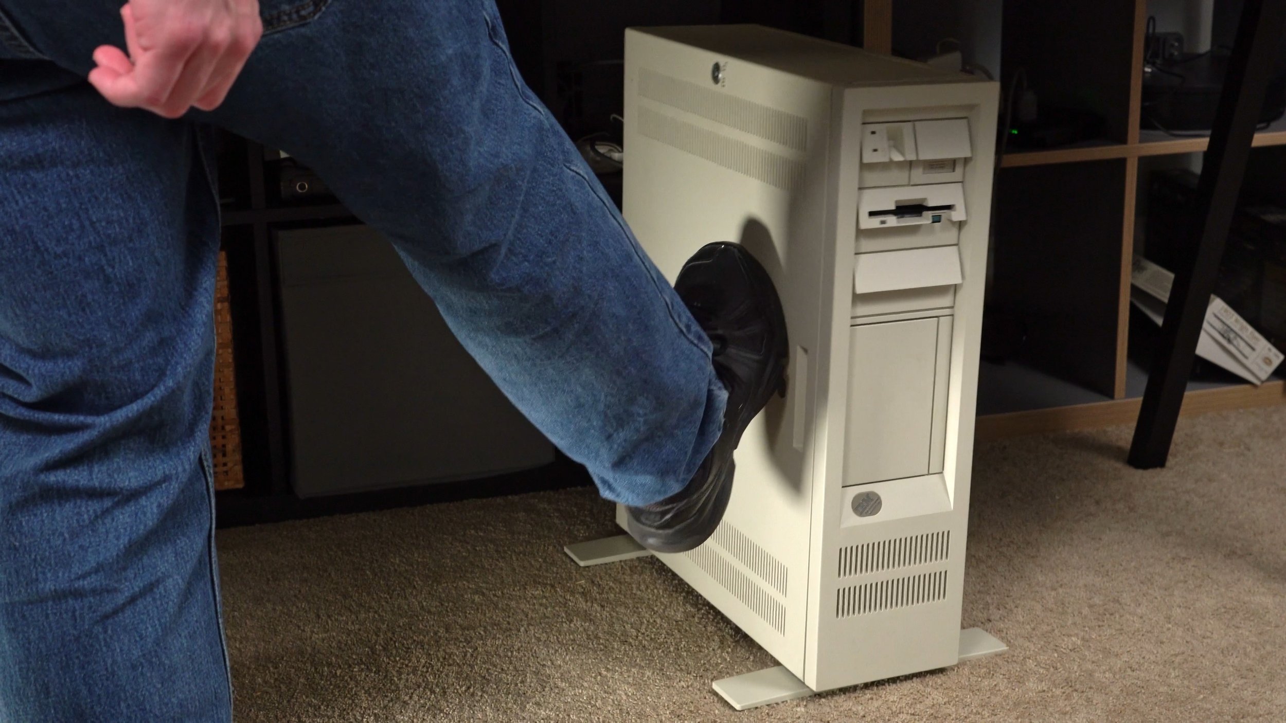
My favorite vintage computing acquisition over the past few years might well be my IBM PS/2 Model 80. It’s an ivory monument to corporate hubris that’s built like a tank and can withstand being run over by one too. There’s something romantic about owning the official PC of “it’s somebody else’s money.” How could I not love this big brute of a box? But they say every rose has its thorn, just like every case has its flaw. And most owners of model 60, 65, or 80 towers have encountered it when installing a CD-ROM drive.

You might remember from the 386 Tower of Power video that these cases have an externally accessible full-height 5 1/4 inch drive bay. A hard drive, floppy drive, tape drive, or any kind of drive can move on up to a de-luxe drive bay in the sky. Just screw on a pair of AT rails on to a drive and slide it on in. But wait—that blanking plate’s only good for hard drives! Installing an externally accessible half-height floppy or CD-ROM drive leaves a gaping hole in the front of the case. Even a full-height optical drive needs a piece of trim to look its best installed in these PS/2s. It’s all because IBM needed to make a compromise.

The original IBM PC 5150’s drive bays were all externally accessible. Therefore all drives, even non-removable hard disks, needed integrated bezels to protect against dust ingress. As hard drives grew in popularity and floppy drives shrank in size IBM changed their bay arrangements with the PC AT. Instead of two full-height (or four half-height) external bays, there were now two external half-height bays and one internal full-height bay. This opened the PC AT up to more hard drive options and eliminated the need for hard drive beauty covers.

But bezels bounced back in a big way when IBM launched the PS/2 line with a new design language. Sharp, angular covers for the new 3.5 inch floppy and hard drives gave these desktops a distinctive look that set them apart from the aging XT and AT. But the Models 60 and 80 ditched the traditional desktop form factor in favor of a tower design aimed at server or workstation customers. These roles had an almost insatiable hunger for storage space, and so any serious machine needed the ability to install capacious full height hard drives or large format removable cartridge disk drives.

To accommodate both types of storage devices in the same chassis IBM devised a clever and innovative solution: they cut a hole in the front of the case. Now either internal or externally accessible drives can be installed in the same bay! IBM figured most customers would install a second hard drive in their towers so a blanking plate is included to keep noise in and dust out. For those that needed removable storage, all they had to do was pop out the blanking plate and slide in their half-height or full height drive. Easy as pie! Unfortunately that leaves you with a small problem: a big gaping hole in the front of the case! How unsightly.

So what do we do with big gaping holes? Why, we cover them up, of course! IBM offered several beauty covers for PS/2 towers starting with their 200MB optical WORM drive introduced alongside the Model 80 in 1987. A half-height bezel soon followed with the CD-ROM and 5 1/4 floppy drive kits. If you didn’t need a whole kit IBM’s service manuals listed part numbers for each bezel so you could call your IBM dealer and order one. But these weren’t the only bezels available! While doing some research to determine when IBM introduced CD-ROM drives as an option for the PS/2, I stumbled across all sorts of PS/2 tower bay bezels. Check out this dual half-height cover used in Tam Thi Pham’s model 80 could cover either a RAID array or clean up a CD-ROM. I wonder if this is IBM official because they bear a striking similarity to Model 95 blanks. Further searching uncovered more interesting half-height covers—even one for slimline drives! And the absolute king is this dual Bernoulli drive on this eBay listing with Iomega’s custom trim ring. This isn’t a hack—Iomega specifically aimed this drive at PS/2 towers! Neat.

But procuring these bezels thirty years after their heyday isn’t an easy task. Most of these trim pieces met their demise when the PCs they were installed in were scrapped. They rarely show up on eBay, and when one does you usually have to buy an expensive computer to get it. So when we can’t find rare and expensive doodads, we go for the next best thing: 3D printed replacements!

Since I still couldn’t find a real bezel by the time I started filming the OS/2 install video, I started looking for printable models. Alas, none were available at the time. A few months later I searched again and found one created by Mike1978, one of the admins of the UK IBM Collectors Discord and all-around cool dude. It would do the job, but my inner perfectionist wanted something that looked more like IBM’s bezels. But I’m not a 3D modeler—my CAD skills never graduated beyond the noodling I did in middle and high school drafting classes.

So I did what anyone lacking in a certain skill does: I posted about it on the interwebs. Back in December I posted on Bluesky asking if anybody local would be interested in collaborating with me on a 3D printable bezel design. My cool (and local) chum GutBomb threw his hat in the ring, but before we even worked out a time to meet up to make some test models I got another reply from the maestro of Micro Channel himself: Tube Time. He came out of nowhere with newly created models for half-height and full-height drive bezels. They even have the little dimples! I’m always surprised by the awesome generosity of this community. Time and again people contribute solutions and fixes to solve problems big and small and they often do it just for the thrill of it. Tube Time, you have my eternal gratitude.

Now that I had a model I could print a bezel. I don’t own a 3D printer, but I do have the next best thing: a buddy who owns a 3D printer! My pal Treble takes on almost any printing challenge and he was happy to oblige with these bezels. After sending him the models I got a box in the mail a week later with some samples. And would you look at that: it’s a perfect fit! It snaps right in to the slot and provides a clean lip above the drive just like the original. I couldn’t be happier!

Well, okay, I could be happier. The fit may be perfect, but the color is not. Treble was limited by the filament colors he had on hand and neither pure white nor bone white are much of a match for IBM’s ivory finish. Color matching is a common problem facing 3D printing enthusiasts, so much so that they end up commissioning custom colors. That’s exactly what Joe’s Computer Museum did with their new platinum filament, but it didn’t exist at the time we were working on these prints. Nevertheless, we can solve this problem with a little bit of rattle can-do attitude.

Painting 3D printed parts is one way to get a better color match, and the truly obsessed would special order a can of RAL 1013 spraypaint. But I wager that most people are fine with “close enough” and I was curious how close I could get with off the shelf paint. I made a trip to the local home improvement store to check out my options. Most of the shades were too white or too beige for my liking, and I wound up settling on Rust-oleum Heirloom White. I’ve been told that Ivory Bisque is a good match for  an IBM, but I couldn’t find it. Regardless, after spending some time in the great outdoor paint booth I think the results are… acceptable. It’s brighter than I’d like and it’s a shade too warm, but it’s a closer match than the pure white or bone white filaments. It’ll do.

With a finished bezel installed I feel like my Model 80 is complete. I can have a real optical drive without an ugly gaping hole, and the color’s close enough for government computer work. I know some folks might wonder why the bezel isn’t fitting flush with the drive, and that’s because IBM’s original bezels weren’t flush fit. There’s variances among various drive manufacturers, and an overlap is a safer strategy than risking a gap. Genuine IBM bezels have nicer overlaps thanks to beveled edges and sometimes rounded corners and reproducing those features on a 3D printer is trickier than sticking to a flat edge. But the upside to 3D printing is that if you want a flush fit you can tweak the model to widen the opening by a millimeter or two to accommodate your favorite drive.

Now, I could stop here and say I’ve completed my quest. But I wasn’t done yet. The original bezels are so rare that increasing the supply is the right and honorable thing to do, and I wanted to match Tube Time’s generosity with some of my own. So I had Treble print out fifteen more bezels to bring to VCF East. I put a little label with an explanation on each one and dropped ten of them on the free pile. They were all gone by the end of Saturday, so clearly they were a hit! I also handed out a few to cool people like Steve and LGR and BigBadBiologist. I feel like a regular Danny Bezelseed here! … All right, that was a stretch. Still, I want these old boxes to look their best, and hopefully folks who picked up the freebies rushed home to install them into their old Micro Channel machines.

So if you find yourself in need of a 5.25 bezel for a Model 60, 65, 80, or Academic System, head over to TubeTime’s page on Thingiverse where you can download a half-height, full-height or blank panel model to fit most any drive you’d like to install. Your tower will thank you for helping it look its best.

IBM's 386 Tower of Power: The PS/2 Model 80

Stand aside. This is a large computer and it takes large steps. Yes, it’s IBM’s biggest, baddest, and heaviest computer of 1987: The PS/2 Model 80 386. If one of these behemoths lumbers into your collection you need to be prepared for all the gotchas it brings. Here in Userlandia we’re adopting a Micro Channel mammoth.

Oh, Micro Channel Architecture. I sure talked a lot about you in the PS/2 Model 30 286 Computers of Significant History video. I had to, really, because a lack of Micro Channel was a defining trait of that PC. To understand what that machine had meant looking at what it lacked. But as I wrote the script, I realized I had a problem: I didn’t own a Micro Channel PS/2. What was I going to use for video footage?

My original strategy was to use still photos and archive footage from my various VCF trips for coverage. I had no plans to buy a Micro Channel machine due to expensive eBay listings and high shipping fees. But I’ve always wanted an MCA PS/2 in my collection, and if I had an opportunity to get one at a good price I’d take it. And wouldn’t you know it, just as I was polishing up the script an alert popped up on my local Craigslist for a working PS/2 Model 80. The machine appeared to be in great shape, with a working SCSI hard drive and a memory expansion card. $200 wasn’t an awful price either. The odds of finding a better deal elsewhere—especially for a machine in this condition—were pretty low. After an hour of hemming and hawing I finally emailed an offer to buy it.

Craigslist Ad for Model 80

Buying stuff on Craigslist or Marketplace can be an adventure, and this was one of the better ones. The PS/2 was located in Townsend, Massachusetts, a bucolic New England town forty-five minutes away from me. I met up with Aaron, who’s a technician at a computer shop. This Model 80 was one of his vintage restoration projects. He cleaned it from top to bottom, fixed a blown tantalum capacitor, and replaced the 6V CMOS battery. We had a great conversation about old computers and his cool Dodge Daytona. I handed him two hundred bucks, he handed me a pack of setup floppies, and I drove this beast home.

I’ll give Aaron extra credit for the effort he put into this machine before selling it. We’ve all been there with people demanding ridiculous sums for something that’s been in a basement for twenty years because they know what they have. A little spit shine and TLC go a long way when making a deal, and as a buyer I try to respond in kind. I don’t want to waste my time or yours, and I’m willing to show up with cash in hand for a sensible price and a good experience.

Aaron’s efforts also made this computer camera ready. The exterior looks like it's fresh out of a detailer. All the icky black foam’s been plucked from the side panel. And look at all these clean, shiny boards! The Model 80 was also mechanically ready and fully configured thanks to a new CMOS battery, a working floppy drive, and a fresh reference disk. When I flipped the power switch the machine booted right to MS-DOS, with some games and a copy of Windows ready to roll. A turnkey experience like this is a rarity in retro these days. Accounting for the value of this work in the price tag makes this a veritable bargain compared to the ones I’ve seen on eBay.

But let’s say you’re not as lucky and you stumble upon a PS/2 that needs some work. A Micro Channel machine can bamboozle seasoned vintage computer collectors with the myriad ways it differs from a regular PC. So I’m going to explore how these machines are built, what they’re capable of, how to upgrade and configure them, and the bumps you’ll hit along the way. I’ve got plenty of knowledge from books and past encounters with PS/2s, but there’s bound to be gaps in my memory. I’d also need resources like disk images, drivers, and ADFs. Luckily, I can stand on the shoulders of big blue giants like The Ardent Tool of Capitalism and IBM Museum. They’re a treasure trove of downloads, documentation, and answers to oddly specific questions. Now that you have an idea of where we’re going, let’s start by exploring the Model 80’s case.

Tower cases were still a rarity back in 1987, and IBM chose to rotate the case 90 degrees because… well, look at the size of this thing! The Models 60 and 80 were designed as floor standing towers that live underneath a desk. Yet despite considerable height and depth it’s fairly narrow compared to most tower cases. IBM was so enthralled with 3.5 inch drives that they designed the enclosure around them. Still, there is a full-height 5 1/4 inch bay—it’s just rotated 90 degrees to fit.

But a big case has a cost, and the price you pay is weight. It’s so heavy that there’s a sticker listing its weight at 40.5 pounds. And this isn’t even the heaviest Model 80 variant! Perhaps IBM took pity on the people who had to port these machines around, because they included a handy handle on the top of the case. I suppose that makes it portable in some way, but I think “liftable” is the better term.

On the bottom of the case are two fold-out pedestal feet. Because the case was intended to stand underneath a desk, there’s a risk that the tower would tip over after an accidental kick from a desk jockey. The cases’s tall, skinny design combined with a top-mounted power supply and heavy drives gives it a high center of gravity. Instead of making the whole case wider—or perhaps as a consequence of designing the narrowest case possible—IBM added these feet to balance things out. You don’t have to use them, but you probably should.

For connectivity, the Model 80 offers a standard array of ports: keyboard, mouse, serial, parallel, and VGA. This makes it easy to hook this old boat anchor up to modern-ish displays and input devices.

Finally, the pièce de résistance: the power switch. IBM may have changed the color from red to white, but it still has that trademark chunky sound. Mmm, satisfying.

Now let’s take a look inside. The side panel is secured by two captive screws, and a coin is the perfect tool to loosen them. There’s a key lock too, but this case’s keys are lost to time. If it was locked, all it takes to open it is cutting the end off a Bic pen and shoving it in.

Normally this panel would be covered in a black noise dampening foam, which over time decomposes into an awful black goo. It’s sticky and gross and irritating and it gets everywhere. Thankfully Aaron removed it all during his restoration. If you’re buying a Model 60 or 80, be prepared for a full de-lousing.

Once you look inside you’ll understand why this computer is so capacious: this case corrals clusters of cards, cages and cables. IBM built this machine to grow along with its customers, and that meant a lot of space for said customers to cram in expensive IBM components. It’s not too chaotic for an enclosure of its era, all things considered. There’s even some basic cable management features.

Storage accounts for most of the volume. The Models 60 and 80 offer “up to six direct storage access bays,” but what does that mean, exactly? That figure includes two externally accessible 3.5 inch bays, one of which is fitted with a 1.4MB floppy drive from the factory. The second bay was free for you to install a second floppy drive, a tape drive, or nowadays a Gotek.

Next is a full-height 5 1/4 inch drive bay. It could hold a floppy drive, optical drive, or a massive full-height hard disk. Installing a drive is straightforward—attach some AT drive rails, slide it in, and tighten the clamp using these thumbscrews. Good luck finding a bezel for most drives, though. Later Model 80s ditched full-height hard drives for a dual drive bracket. Buy a second one and—ta-da—you now have the advertised maximum of six drive bays.

A lot of drives will draw a lot of power, and a 242 watt power supply feeds all these components. That might not seem like much compared to modern workstations, but it was pretty good for its day. PC ATs maxed out at 192 watts, while desktop PS/2s offered something between 90 and 132 watts. All this juice flowed through fully modular cables, which was another rarity for the era.

What if you needed to replace a dead drive or a faulty power supply? Taking apart these towers is easier than you’d expect because they were designed to be serviced on site by corporate IT techs. The first step is to remove the front bezel. It comes off with a solid pull from the bottom, just like many modern PCs. The 3.5 inch bay covers are held in with clips and pop out easily by pushing in at the edge, and the same goes for the 5 1/4 bay bezel.

Like other PS/2s the floppy drives are attached to sleds. Unplug the floppy cable, press upwards on the tabs, and it slides right out of the case. Next is the hard drive bracket. This is easy—just loosen the thumbscrews and the bracket slides back for removal. Hard drives are installed using standard drive screws. Four screws secure the drive bay carrier to the chassis. Use a nut driver or a big flathead screwdriver to loosen them. Once the screws are removed, the bay carrier lifts up and out of the case. The power supply is just as easy. First, unplug the motherboard cable. Then unscrew the three screws securing the power supply to the chassis. Now you can grab this handle and pull up.

With all those components removed we’re left with a sizable motherboard. IBM made three different versions of the Model 80 planar, and this one’s a type 2. It’s distinguished by two ROM BIOS chips versus the type 1’s four chips, and three 32-bit MCA slots versus the type 3’s four slots. Google the FRU number if you’re unsure.

Processing power comes from a 20MHz 386DX CPU and 387DX FPU. There’s no cache on this board; that was reserved for the 25MHz type 3.

Memory for the Model 80 comes in the form of these planar memory cards. IBM shipped these -081s with one 2MB card, and this example has a second 2MB card bringing the total to 4MB. Up to 8MB could be installed on this planar via two 4MB memory cards. Finding them isn’t easy, so you might have better luck installing Micro Channel RAM expansion boards.

Here’s a neat curiosity: an add-on floppy controller plugged into the planar’s floppy port. I haven’t been able to identify this specific board or find any documentation for it, but based on the jumpers my hunch is that it came with a tape backup kit. Attached to its secondary port is a long ribbon cable that leads to a slot bracket with a 37 pin external floppy connector. Presumably this would work with the IBM External 5 1/4 inch drive, but I don’t have one to test this theory. I’m also curious if it supports more than two floppy drives, as the standard dual-drive ribbon cable is still attached to the primary port. If you have any ideas, leave me a note.

Video is provided by IBM’s base PS/2 VGA graphics chipset. A VGA controller, 256K of video memory, and an Inmos RAMDAC deliver standard VGA graphics modes like 320x200 at 256 colors.

Unlike my Model 30 and its Dallas clock chip, the Model 80 has a separate battery for its realtime clock and CMOS memory. It’s a common 6V lithium camera battery that costs around ten to fifteen bucks to replace. These machines won’t boot without a working battery, so make sure to put one on your shopping list.

Lastly, it’s time for slots and cards. Micro Channel Architecture is the defining feature of these PS/2s, and you’ll need to learn its intricacies before planning any upgrades. This Model 80 came with three cards: an IBM Token Ring Adapter, an IBM PS/2 SCSI Adapter, and an IBM Enhanced 32-bit Memory Adapter.

Before adding or removing any cards I suggest you make a note of your existing configuration. Adding, removing, or changing cards will force you to run the reference disk’s configuration utility at the next boot. I’ve got the memory card in slot 2, SCSI card in slot 4, and token ring card in slot 7.

Installing Micro Channel cards is pretty easy. Unlike ISA and PCI cards which are secured by regular screws inside the case, MCA cards are secured by thumbscrews that are outside the case. I find them a bit fiddly for my fingers, but the ends are slotted so a screwdriver or coin makes quick work of loosening them. Then each card can be lifted up and out of the case thanks to these plastic guide pieces.

Another difference between MCA and other types of cards is the bracket. One of the reported flaws of the classic card bracket is that it’s not great at stopping electromagnetic leakage. Micro Channel brackets are designed to slide into, well, metal channels forged in the back of the case. A set of springy fingers on each side of the bracket grip the channel sidewalls and connects a solid ground.

With all the cards removed we can see three different types of MCA slots. This planar has three 32-bit slots with matched memory extension, four standard 16-bit slots, and one 16-bit slot with Auxiliary Video Extension. Notice that despite their varying lengths that all the slots are aligned to this one key pin. A 32-bit slot has a longer connector than a 16-bit slot, but since the key pin is in the same location, a 16-bit card works in a 32-bit slot. Some 32-bit cards can be used in 16 bit slots if they have a compatibility key—just make sure the hanging edge connector doesn’t interfere with other components.

Extensions aren’t just for bit width, either. Check out this one on the front of slot 6: it’s the Auxiliary Video Extension, yet another evolutionary dead-end for PC graphics. Imagine you’re buying a PC to run CAD applications in the mid-1980s. Basic CGA and MDA graphics cards weren’t up to snuff, so you’d buy a dedicated graphics card and a matching monitor. But you can’t get rid of your original video card and monitor, because that expensive new card and monitor can’t display those old modes! So your original graphics card and monitor would live side-by-side with your new graphics card and monitor, usually with text on the former and graphics on the latter.

IBM’s fist attempt at solving this problem was the beast known as the Professional Graphics Controller, or Adapter, or Array. This triple-decker circuit board sandwich layered with chips and controllers served up analog RGB video at 640x480 resolution with 256 colors out of a palette of 4096. But that’s not all—it also emulated CGA graphics modes over the same analog output! This meant you could run Lotus 1-2-3 and AutoCAD on the same monitor without needing to flip switches or change inputs.

So when you look at the PGC and its layers of complexity, you can see the logic behind the AVE. If IBM was already including a VGA chipset on every PS/2 motherboard, why not use it? Installing an AVE card trips a presence switch that enables a digital passthrough for the onboard VGA graphics. Whenever a CGA, EGA, or basic VGA mode is requested, the planar’s VGA is routed through the AVE to the add-in card’s monitor port. If you’re thinking “Wait a minute, that sounds suspiciously similar to how 3dfx cards passed through VGA signals from a 2D graphics card,” you’re not wrong! The execution’s different, but the spirit’s the same.

There’s nothing technically wrong with AVE, but it was doomed to fail. Partly because it was a Micro Channel exclusive and Micro Channel failed, but mostly because IBM underestimated the power of Moore’s law. Makers of graphics board took advantage of the rapid pace of technological advancement to soup up VGA into more powerful Super VGA cards that could display standard modes and their higher resolution modes without passthroughs. Even IBM had to admit it was a dead end when they integrated VGA support into XGA. But that’s enough about video for the moment. Let’s examine the cards that came with this system.

First and certainly least is a Token Ring 16/4 Network Adapter. IBM’s version of Token Ring is probably the most famous—or infamous—ring topology network. Setting up a simple Token Ring network isn’t easy, because an Access Unit is required for even the simplest scenario of connecting two computers together. Stay tuned, because I have a different solution for getting this machine on a network.

Next is the IBM PS/2 SCSI Adapter. It’s better known by its codename Tribble, as it’s one of two SCSI cards with Star Trek names. The other Star Trek SCSI card—Spock—has cache memory which, logically, should yield better performance. Model 80s won’t see much of a benefit from the cache, so a Tribble card is fine. A ribbon cable attaches to the top edge connector and provides three 50-pin connectors for internal drives. The external connection is, annoyingly, a proprietary IBM HDCN-60 pin connector. That means no external CD-ROM or Zip drives without finding a unicorn cable or adapter. At least an internal BlueSCSI can serve as a CD-ROM emulator.

Lastly, we have the IBM Enhanced 80386 Memory Adapter with ROM. This long board with the longer name is a great example of IBM’s penchant for proprietary peculiarities. Model 80 planars are limited to a maximum of 4 or 8 MB of on-board memory depending on your particular variant. Further memory expansion requires a Micro Channel memory expander from IBM or third parties like Intel, Kingston, and so on.

One downside to IBM memory adapters is that they require IBM-branded SIMMs. The system checks for presence bits on the SIMMs that match specific combinations of speed and size, and if it doesn’t find them it’ll error during POST. I bought a pair of IBM 4MB 70ns SIMMs because various sites and newsgroup posts claimed the part number was compatible. 70ns SIMMs should work in an 80ns system; they’ll just run at 80ns. Yet after I installed them the PS/2 returned an 18441 Unsupported SIMM error.

The seller had validated them as working IBM SIMMs, and I had no reason to doubt them because I’ve bought plenty of good RAM from them before. And yes, I tried it with only the 70ns SIMMs installed. Maybe 70ns SIMMs only work in this card when it’s installed in a type 3 planar, which requires 70ns RAM. I eventually gave up and bought two 80ns SIMMs that matched the one I already had, and those worked fine.

Now I have 16MB of RAM, which is great for DOS and Windows 3.1, and probably acceptable for OS/2. Coincidentally, 16MB is the soft limit for RAM in a Model 80. Yet another quirk of this machine is the 24-bit direct memory access controller, which means any DMA transfers must occur in the first 16 MB of RAM. If a bus-master card or an OS performs a DMA transfer above that barrier, well… brace yourself for a crash. That’s a bit of a bummer for a machine like the Model 80 which is designed around DMA and bus mastering.

But where there’s a will to install more RAM, there’s a way. IBM released the Bypass One Problem Temporarily patch, which updates the reference disk and the ROM on this card to work around the 16MB limit. The requirements for this are a bit arcane—you’ll need at least two MCA memory adapters, one of which has ROM. I highly recommend reading a copy of the update instructions posted by Ian Brown on the comp.sys.ibm.ps2.hardware newsgroup. I updated my adapter by following these instructions and the process was tedious but straightforward. Pro tip: save yourself from dozens of disk swaps and extract the updated ADFs and SC.EXE from a disk image and copy them to your reference disk using a modern PC. If this is too hacky for you, boards like the Acculogic and Kingston memory expanders have their own memory mappers and can break the 16MB barrier without BOPT according to PS/2 wizard Peter Wendt. My advice is to avoid this problem entirely and stick to the maximum 16MB of RAM.

Imagine that you’ve finished restoring a PS/2 just like this one. You’ve replaced the CMOS battery, upgraded the memory, serviced the drives, and stuffed all those cards into its slots. It’s be a big white doorstop unless you have the key to start it: the reference disk. Every MCA PS/2 has a Reference Disk with utilities and configuration files to set up its BIOS, and you’ll need to fish it out whenever hardware changes are made. Odds are it’s not the only disk you’ll need either thanks to the architecture of IBM’s software device configuration.

Plug and play systems need a way for the BIOS or operating system to identify hardware, and IBM’s idea was Programmable Option Select. POS uses eight hardware registers to declare the card’s identity and capabilities. The first two contain adapter and manufacturer information encoded into a unique 16-bit identifier. The next four are programmable option registers that use bit masks to define the card’s option settings. They’re like a software version of DIP switches or jumpers that let you virtually select configuration options like an IRQ or address port. The last two are subaddress registers which can read or write data to additional memory on the board. I’m glossing over a lot here, but if you want more gory details about MCA’s architecture I’d recommend checking out the sources I used for research: Tube Time’s MCA Tutorial or the MCA Architecture Handbook on Archive.org.

POS’ fatal flaw—unfortunate abbreviation aside—is that it doesn’t actually tell the BIOS much of anything about the card other than the unique ID. A few reserved option bits have fixed functions defined in the spec, but otherwise you’d have no idea what a card is capable of just by looking at the registers. That’s why every card needs a matching Adapter Description File. ADFs are text files which translate the unique ID into an actual card name and the option registers into settings like IRQs and I/O addresses. Without ADF files MCA cards are worthless. Back in the day these files came on Option floppies, or you could download them from a BBS and copy them to your reference diskette.

How does software configuration work in practice? Let’s demonstrate by trading out the Token Ring card for an Ethernet card; specifically this Western Digital EtherCard Plus 10T. After installing the card I’ll need to boot up with the reference disk.

God, the memory test on this is slow.

The system recognized that the adapter configuration has changed andI’m prompted to run automatic configuration. Normally this is when you’d use Copy Option Diskette to load the ADF, but I’ve already copied the ADF to the reference disk using a modern PC. The auto-configuration process takes a few minutes, and when it’s done you’re dropped into the reference disk’s main menu.

Looking in View Configuration the ethernet card shows up in slot 7 and we have some settings to tweak like its I/O resource, IRQ, BIOS ROM, and so on. This is POS working as designed, automatically selecting the appropriate resources based on the installed cards. Seems pretty easy, so why does everybody grouse about it?

It’s not that POS doesn’t work; it’s that it doesn’t go far enough for something that breaks backwards compatibility. POS might have eliminated jumpers and switches but it didn't solve the architectural issues that made them necessary in the first place. There’s still the potential for resource conflicts with an unlucky combination of cards. It doesn’t matter if the system can auto-assign an IRQ when the only one the card can select is 7. Then there’s the tedious reference and option disk shuffling, which nobody liked then or now. If my reference disk was lost or destroyed I’d have to re-copy all the ADFs and re-do all my custom configurations. That ethernet card didn’t come with an option disk when I bought it at a swap meet. If I hadn’t found its ADF over at the Ardent Tool, it would be utterly useless.

On the one hand IBM was working within the constraints of its era, which makes some of these decisions understandable. But on the other hand NuBus and Zorro were true plug-and-play busses, and they were developed and released at the same time! At least Micro Channel gave a blueprint for mistakes to avoid when the PCI group got around to defining the PCI configuration space.

But whatever. You’ve successfully restored and configured a Micro Channel monolith. Only one question remains—what are you going to do with it? I can hear all the shouts of “GAMES! PLAY SOME GAMES!” But look at this thing—people weren’t buying them for games. This particular Model 80 is a type 8580-081, which was announced on October 30, 1990 for a list price of $6,845—that’s almost $16,000 in today’s purchasing power. That chunk of change bought you a 20MHz Intel 386DX, 2MB of RAM, a 1.4MB floppy drive, VGA graphics, and an 80MB SCSI hard drive.

With such a lofty price tag, the only way someone could afford a machine like this was to put it to work. And wouldn’t you know it, I’ve got a productivity app perfectly suited to pay those bills: AutoCAD! Behold as it slowly paints the famous Autodesk Space Shuttle demo file line by line. I won't guess how long an actual render job would take. Honestly, this machine’s performance in Windows 3.1 is more than acceptable, even within the limitations of cooperative multitasking. 16MB of RAM and a SCSI hard drive certainly help on that front. But could I be even more productive with a higher resolution display with extra colors? If only there was a way to… extend the graphics capability of this machine. Wait a minute, there is! It’s the IBM XGA-2 graphics adapter!

This card is notable because it was IBM’s last-gasp attempt to stay in charge of PC graphics standards. Introduced in September 1992, it improved upon the first XGA card by upgrading the VRAM to a standard 1MB, adding support for 800x600 resolutions, and offering non-interlaced 1024x768 modes. And XGA-2 did all this for a list price of $360, which a fraction of the $1,095 you’d pay for a 512K XGA-1 back in 1990.

Installing this card opens up a new world of video capabilities. A graphical OS is a much better experience with a large 1024x768 desktop with 256 colors and a flicker-free 70Hz. Or I can trade resolution for color depth and get 65,000 colors at 640x480 or 800x600. And fixed-function graphics acceleration routines prevents all this pixel-pushing from pulverizing performance. This chipset had all the ingredients to succeed VGA as the de facto PC graphics standard—so why did it fail?

When IBM launched XGA in 1990 the landscape of PC graphics was shifting constantly. VGA was a massive improvement over CGA and EGA, but the hunger for higher fidelity graphics seemed insatiable. Companies like Genoa, Western Digital, and ATI released so-called Super VGA cards that displayed more colors or higher resolutions than regular VGA. Some Super VGA cards were clones of IBM’s 8514/A, the predecessor to XGA. Others extended VGA in their own ways which required specific drivers for each application. SVGA wasn’t really a standard; it was just a label that meant “somehow better than VGA.” IBM’s plan with XGA was to define a real successor architecture, publish the hardware specifications, and license out the chipset. Other manufacturers adopting XGA would kill the incompatible Super VGAs, just as VGA did to the Extended EGAs of yore.

That was a sensible strategy in 1987, but IBM’s influence had waned by 1990. Video card and monitor manufacturers agreed to work together and formed the Video Electronics Standards Association in July 1989. Going forward VESA would define a vendor-agnostic method to display Super VGA modes. The first round of VESA Video BIOS extensions released in 1990 had their limitations, but it was a sign to application developers that the madness of writing a driver for every video card would eventually come to an end. Now they could request a VESA video mode and either the card’s VBIOS or a terminate-and-stay-resident program would answer the request by changing the graphics card to the desired mode.

IBM was a member of VESA and XGA cards do support VESA modes thanks to an IBM TSR. But the catch is that IBM expected developers using VESA modes to obey the spec, and—surprise—most did not. Many apps and games directly manipulated the VGA color registers while in VESA modes. XGA’s high resolution modes don’t use the VGA palette registers, so attempts to modify them results in a corrupted palette. IBM’s TSR ends up being useless. Meanwhile, UniVBE just hangs, so there isn’t really an alternative.

The practical impact of this problem on a Model 80 is minimal because the number of games than run on a 386 with Super VGA graphics can probably be counted on one hand. The two most popular would be Links 386 and SimCity 2000, and luckily they both have XGA compatibility switches. 486 PS/2 owners with XGA will face more challenges. According to old newsgroup posts the VESA emulation in Windows 95 actually fixes the palette problem, so you might have better luck running DOS games in Windows instead.

If VESA had adopted XGA, maybe things would have been different, but IBM admitted defeat in 1993 when they switched to Cirrus-based SVGA chipsets and cards. Will an XGA-2 card help your MCA PS/2? It couldn’t hurt, especially if you like to run Windows. There’s updated drivers for Windows 9x that enable more color depths at higher resolutions. If your goal is pure DOS gaming, you might want to look elsewhere. But adding it to this Model 80 feels right. This machine deserves better than VGA graphics, and now it feels more complete.

I hope you enjoyed my tour of this monument to business arrogance. I’m not an IBM fanboy, but I have to say there’s a devilish appeal to owning something that was way out of your price range when it was new. Aaron and I agreed that if I was going to own a Micro Channel machine, this one had to be it. The only way I could make this thing even more IBM is by installing OS/2, and maybe I will some day. Until then, it’ll stay in my collection as a piece of Big Blue history.